
Simo motors successfully solved the rotor open-circuit fault of a mining company's JR series wire-wound motor.
Date: 2023-08-21 Categories: Cases Views: 964
Excerpt:
This article records in detail the whole process of repairing the open-circuit rotor winding of JR137-4 type wire-wound motor for a large mining company by the professional technical team of Simo Motor. Through accurate fault diagnosis and professional winding process, we not only solved the rotor winding open-circuit problem, but also established a perfect equipment health management system for the customer through a comprehensive preventive maintenance program. This case demonstrates the technical strength and service quality of Simo Motor in the field of JR series wire-wound motor repair.
Article Catalog[Hidden]
- I. Fault Background: Production Interruption, Urgent Assistance Requested
- II. In-Depth Diagnosis: Pinpointing the Fault Location
- III. Professional Maintenance Plan and Implementation
- IV. Maintenance results and customer value
- V. Case Summary and Technical Extension
- VI. Simo Motor's Professional Advantages
I. Fault Background: Production Interruption, Urgent Assistance Requested
Customer Information:
- Client OrganizationA large mining group's mineral processing plant (name withheld at client's request)
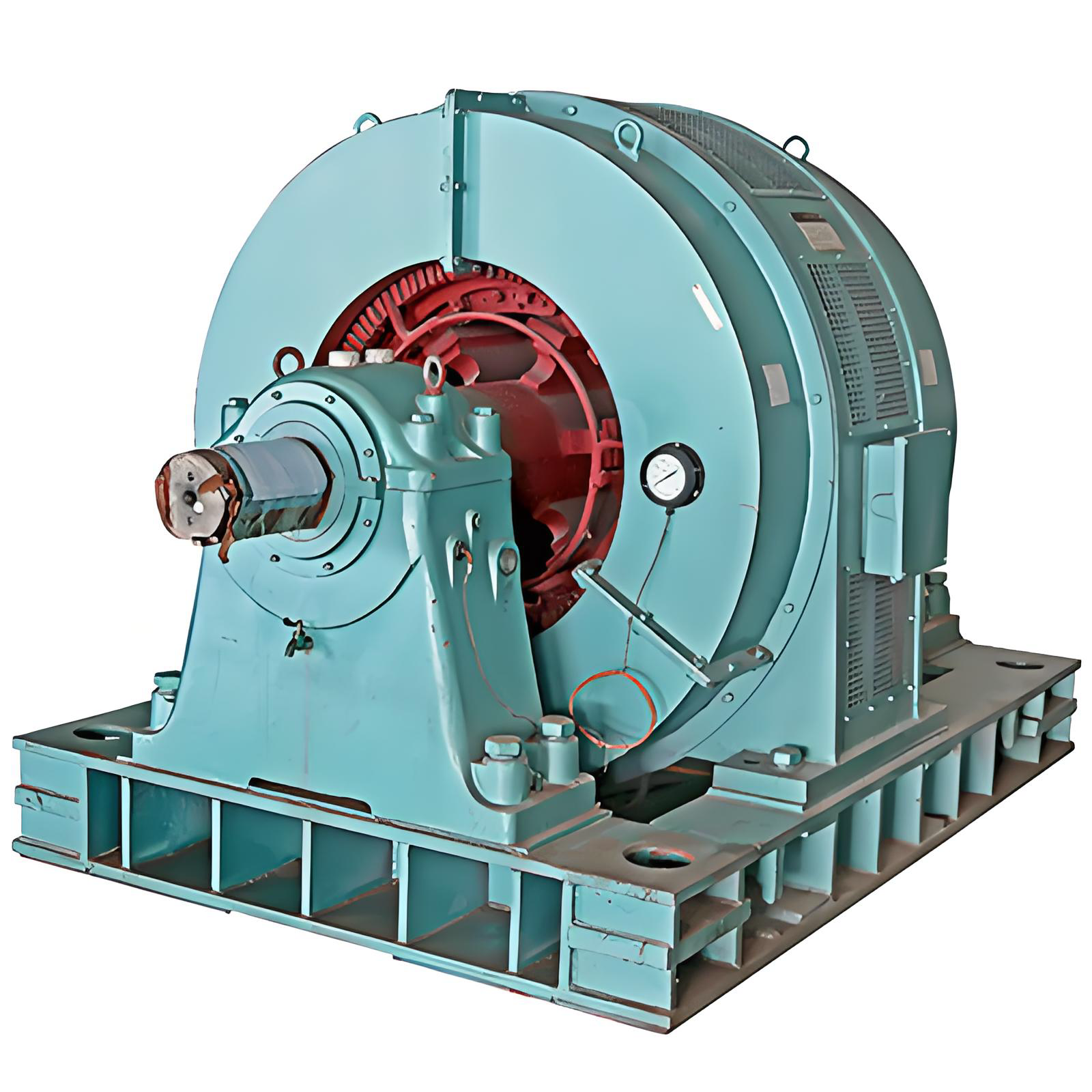
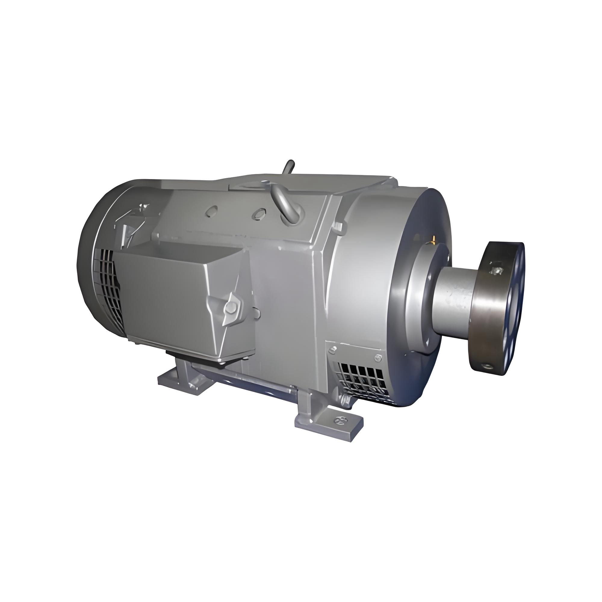
- Equipment TypeJR137-4 Wound-rotor Induction Motor
- Key ParametersRated power: 220 kW Rated voltage: 6 kV Rated rotor voltage: 275 V Rotational speed: 1480 r/min
- application scenarioCore Ball Mill Drive Equipment
- Fault Symptoms:
- Sudden shutdown during operation; motor fails to restart.
- The electronic control system displays "Rotor circuit abnormality."
- The slip ring area exhibits distinct discharge marks accompanied by a burning smell.
II. In-Depth Diagnosis: Pinpointing the Fault Location
Simo motorsUpon receiving the service request, the technical team responded immediately and arrived on-site within 4 hours to conduct system diagnostics:
1. Preliminary Detection and Analysis
- Using a multimeter to test the three-phase windings of the rotor, an open circuit was detected in the B-phase winding.
- Insulation Resistance Measurement: Rotor winding insulation resistance to ground is 0.8 MΩ (standard requirement ≥ 1 MΩ).
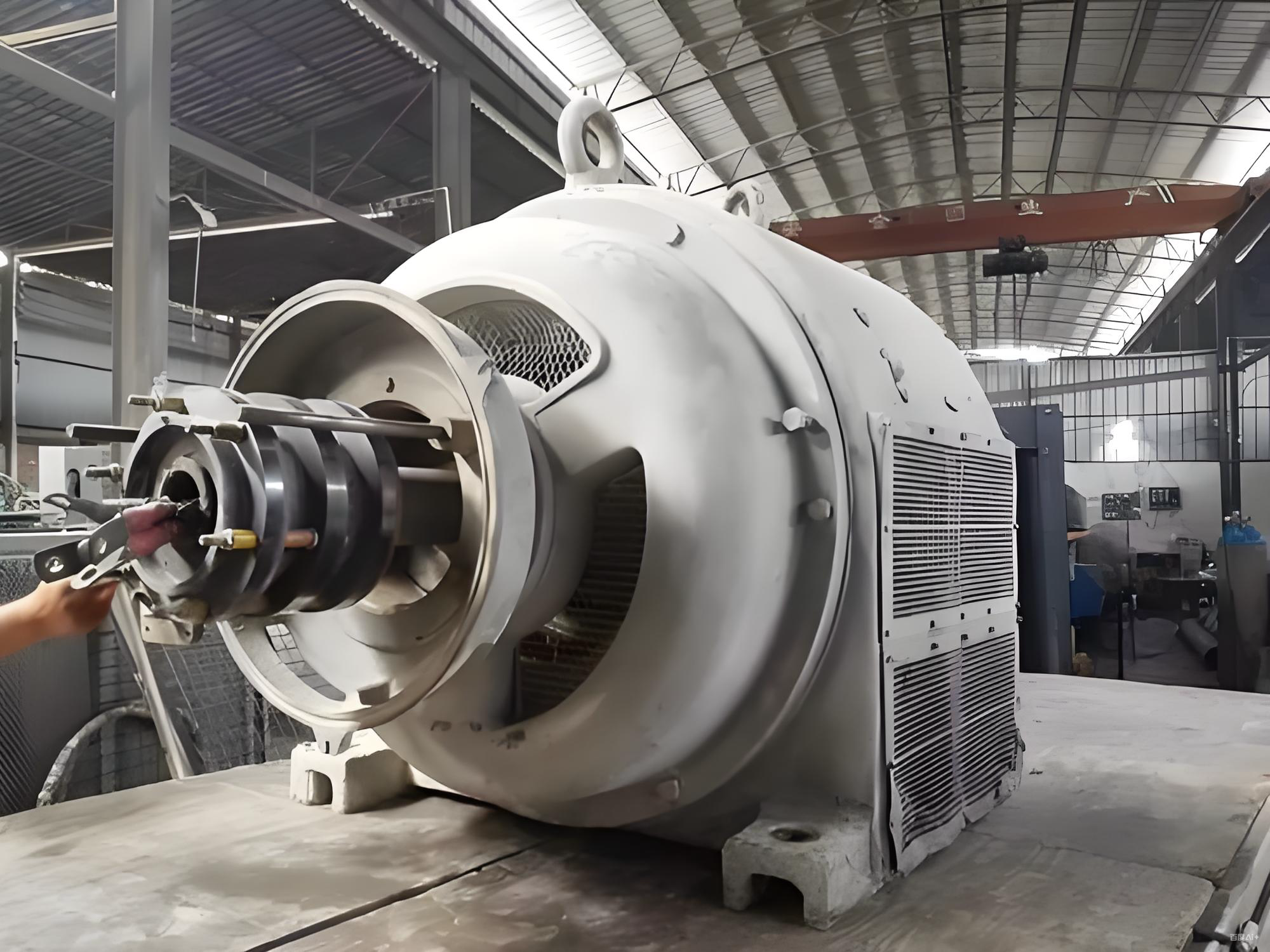
- Inspecting the slip ring assembly: One of the slip rings was found to have severe surface burn damage.
2. Precision Diagnostic Localization
- Perform scanning inspection using a winding interturn tester
- Performing temperature distribution analysis on rotor windings using a thermal imaging camera
- Fault Pinpointing:
- The lead wire of the sixth winding in phase B of the rotor winding has broken.
- The welded joint between the slip ring and the winding has burned out.
- The slip ring surface exhibits uneven wear reaching 1.2 mm.
III. Professional Maintenance Plan and Implementation
Based on the diagnostic results, we have developed a specialized repair plan:
1. Rotor Winding Repair
- Detailed TeardownCarefully remove the faulty coil using specialized tools, taking care not to damage the iron core.
- Winding Repair: Rewind the coil to the original specifications, using F-class insulation material to enhance the heat resistance rating.
- Welding ProcessUse silver-phosphorus copper solder to ensure reliable and secure connections.
2. Slip Ring Assembly Repair
- precision machiningPerform precision turning on the slip ring surface to restore standard surface finish.
- Carbon Brush ReplacementReplace all carbon brushes and adjust spring pressure to standard value.
- Enhanced InsulationInstall a reinforced insulation sleeve between the slip ring and the shaft.
3. Professional Process Control
- Dynamic Balancing CalibrationCalibrated on a dedicated balancing machine, residual unbalance < 1.0 g·mm/kg
- Vacuum impregnation: Utilizing the VPI process to ensure thorough penetration of the insulating varnish
- High-temperature curing: Strictly follow the process curve for temperature ramping and curing.
IV. Maintenance results and customer value
1. Verification of Repair Effectiveness
- The test run after repair was successful on the first attempt.
- Rotor three-phase DC resistance balance ≤ 1%
- Insulation resistance restored to over 500 MΩ
- Parameters such as temperature rise and vibration exceed standard requirements.
2. Value Creation
- Rapid resumption of productionRepairs completed within 36 hours, reducing production downtime losses by approximately 800,000 yuan.
- Performance Enhancement:
- Motor efficiency improved by 3.21%
- Annual electricity savings are projected to reach approximately 45,000 kilowatt-hours.
- Carbon brush lifespan extended to twice the original duration
- Management OptimizationAssist in establishing a dedicated maintenance plan for the rotor system.
V. Case Summary and Technical Extension
1. Key Points for Maintenance of JR Series Motors
- Wound-rotor motors require particular attention to the coordination between the rotor windings and the slip ring system.
- Regularly inspect the wear condition of carbon brushes and spring pressure.
- Monitor the formation status of the oxide film on the surface of the slip ring
2. Preventive Maintenance Recommendations
- Daily Inspection:
- Check the carbon brush wear daily.
- Measure the insulation resistance of the rotor windings weekly.
- Inspect the surface condition of slip rings monthly.
- Professional Maintenance:
- Perform rotor dynamic balancing verification every six months.
- Annual winding interturn insulation testing
- Establish a Rotor System Operation Record
VI. Simo Motor's Professional Advantages
This case study demonstrates Simo Motor's expertise in the repair of wound-rotor motors:
- Professional equipment:
- Equipped with large dynamic balancing machines and VPI impregnation equipment
- Equipped with professional winding machines and testing instruments
- Technical Team:
- With over 20 years of experienceWound Motor RepairExperience
- Holders of Electromechanical Professional Qualification Certification
- Process Standards:
- Strictly implement the ISO 9001 Quality Management System
- Adopting internal process standards that exceed national standards


 Shaanxi Public Security Bureau No. 41032502000206


